
-Jump to Helmet section
-Jump to Backpack section
-Jump to Cool shirt section
-Jump to Audio section
Space Suit Build
10/01/14
NEWS
04/26/15
Much to my dismay, I did not complete the space suit in time for MegaCon. Despite working for long hours every night after work and on the weekends, there simply wasn't enough time to finish it. I'm not giving up on it, though. I'll finish it and wear it next year at Megacon. The advantage is, I get to make sure everything it functioning properly. It was a huge blow seeing all of the great costumes at Megacon, but such is life when you have to work full time. I'll keep posting the details below. There are new ones there now.
End NEWS
I came up with the idea for a space suit build after visiting NASA, which is just down the road. I wanted a really good costume, though. On a scale of 1 to 10 with 10 being more or less a real space suit, I was shooting for an 8 or so. This suit isn't cheap to build this way, but there are ways to make it cheaper and I'll try to point them out as I go. If you are into cosplay, then you should have all of the skills necessary to construct this suit. Sewing is a must on this suit, so if you can't do it, find a friend that can. Welding skills are handy but not necessary to do the job. You will have to be comfortable drilling and bolting things together as well as gluing and perhaps some tapping of holes. A little ingenuity never hurts so feel free to make changes to the parts and method according to your own taste. If you have any questions, don't hesitate to contact me at antimatterstore@gmail.com.
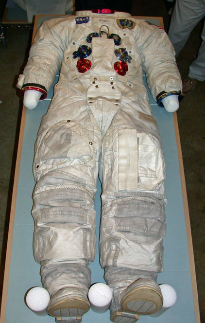
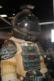
While I'm not building a replica, I still needed a model. NASA had several to choose from in the Atlas V building at Kennedy Space Center, but I found this online which was awesome because there were a lot of close up pictures. It's almost as if they knew I was going to build my own.
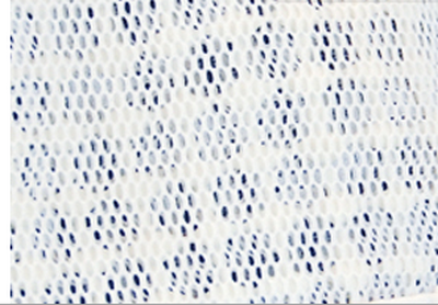
If I were building a 10 out 10 suit, I suppose the actual suit would be made from scratch. I have a confession. I don't sew. My wife tells me it's actually easier to build the suit from scratch than it is starting with coveralls. Blast! At this point, I have just bought a pair of coveralls to use as a base. Normal coveralls were hard to get just right, because a lot of them have a button down collar and I couldn't see how to attach the helmet and make it look right. Finally I stumbled on bee keeper's suits, which looked a lot like space suits right away. There were some issues, though. Many bee keepers suits are virtually perforated in order to make the suit breathable. The material looks like the one below. And how exactly does this keep a bee from stinging you?
 It is hard to tell from the pictures on the net so be careful when choosing coveralls to use as a base. Ask the manufacturers questions and get close up pictures if you can. Another issue is of course, price. Many of these suits start over $100. I tried to keep my costs down and finally found this one.
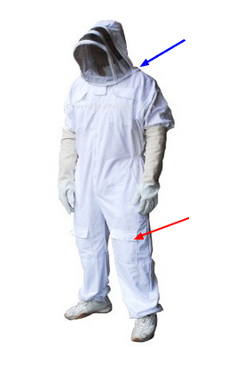
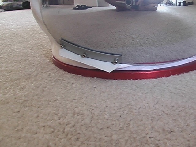
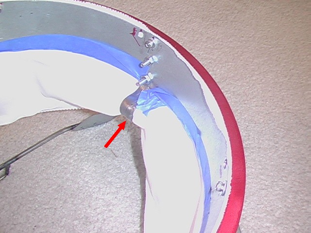
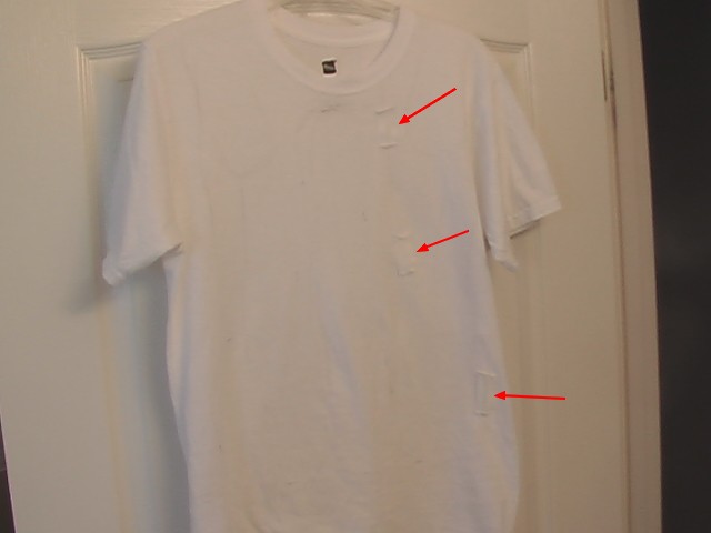
I liked this suit because of the pockets on the lower legs (red arrow). They look a lot like real space suits. Also, the hood can come completely off and is held on by a zipper (blue arrow). So if I put the helmet ring on the hood side, I can just zip it to the suit. Perfect. I bought it here Pestmall.com for $75.00 with free shipping 10/04/14. As it turns out the two pockets were really higher up on the suit and so don't look quite as good, but it is still a good suit. Also, they run very small. I ordered mine two sizes larger, so that it would appear large. That was just about right. I should also mention that in some of the reviews the only negative comments were that the zipper that holds the hood on, kind of sucks. Mine seems ok and I don't expect to remove it too often, but I will report back if anything fails. The suit is part cotton part polyester.
There are some obvious challenges with making this costume. The valves and rings around the neck and arms are the most obvious ones. These could be made out of plastic but to me that would be more of a 5 out of 10 suit. This man made his own and did it on the cheap. It looks pretty good online but I think up close it wouldn't stand up to scrutiny for my purposes (no offence to Greg B.), plus I think the helmet is way too large: Greg B.'s Space Suit.
There's a reason for that. A round piece of plastic the right size and shape isn't easy to come by. His solution was to purchase a light with a round globe so I guess the size was close enough. More on that in the helmet section.
The beauty of this costume is a full suit can be made and worn in pieces. This helps spread the financial burden over a few builds. There is the main garment that can be worn by itself. Then gloves could be added. Then a helmet. Then a Snoopy cap. Then a backpack. And finally add-ons, like lights and cameras. Unless you are making a replica the sky is the limit as far as how it looks and what you do. It could look like a NASA suit or it could be as bizarre as the suits from the movie Alien.
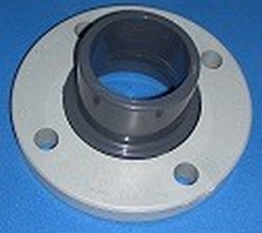
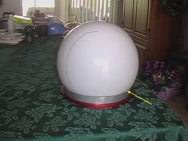
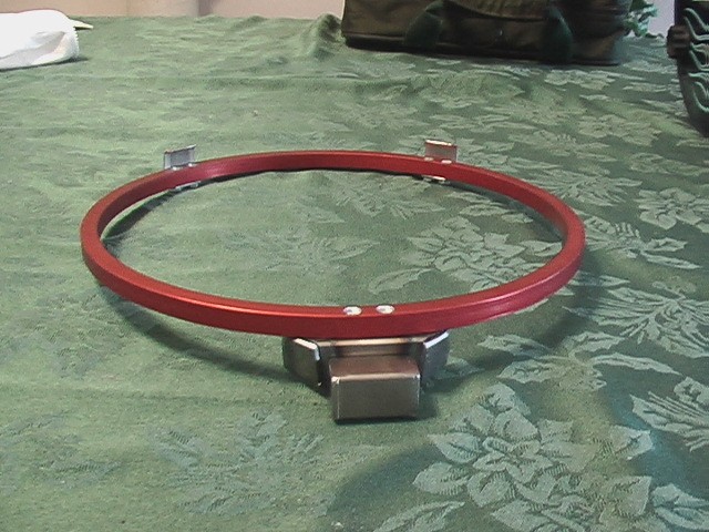
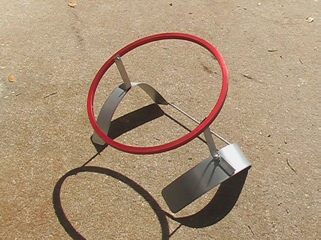
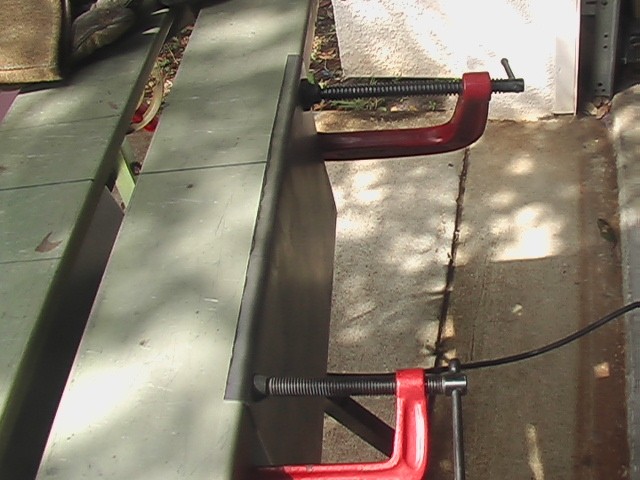
For the neck ring, there were some problems. First, I wasn't really sure how big it should be. Too small and it wouldn't go on over my head and too large it wouldn't look right. I figured 10 to 12 inches would be about right and that I could live with something a little too big if that was all I could find. I tried searching the net for aluminum rings, but kept coming up with rings you could wear on your finger. Other search terms just didn't pan out. Finally I came up with the brilliant idea of having a piece of pipe cut. A little sliver would be all I would need. I found the answer here: Onlinemetals.com. They offer aluminum pipe in sizes as large as 10" diameters. FYI the difference between pipe and tube is that pipe is measured using the internal diameter (ID) and tubes are measured using the outside diameter (OD). Because 10" was the maximum I could get, I ordered one that had a length equal to its wall thickness, which in this case was 0.365" so that it's cross-section was roughly square. When it arrived it was perfect. In fact, I think 12" would have been too large. Nine inches may work, but it could be a bit small for larger heads. So if you wonder how big the neck ring should be, I think 10" is it. You'll want this one: 6061-T6 10" Schedule 40 Aluminum Pipe. There is a 'create custom size' tab toward the middle where you can put in your size. It looks like they charge by the inch, but you can put in less than an inch. I bought two of them, one for the suit and one for the helmet. The cost was reasonable at $14.92 each, but there was a shipping charge so the total was $46.42, more than I would have preferred to pay but unless you can find a more suitable option, this is it. Here's what it looks like:

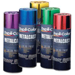
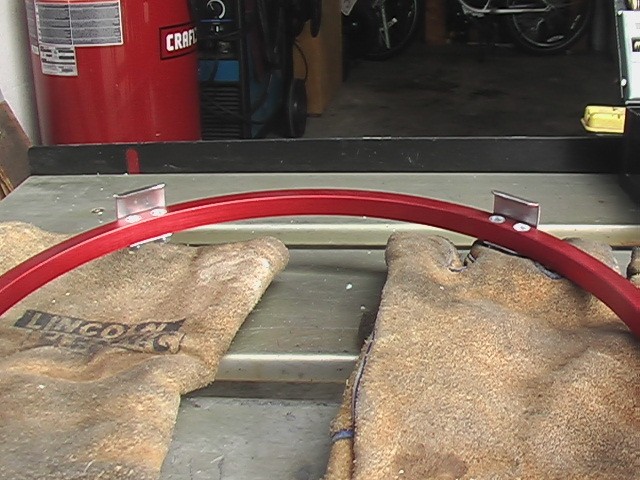
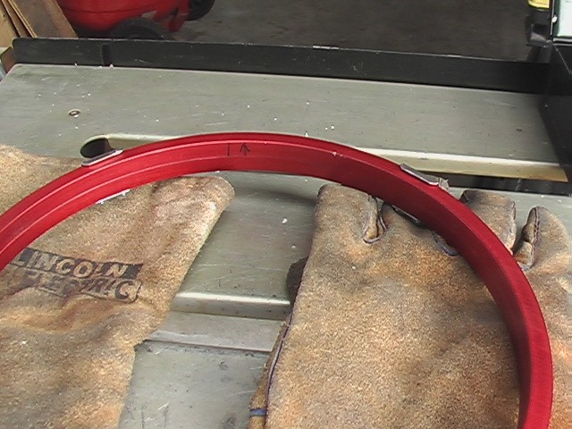
They came with really sharp edges and pretty rough finish, so you'll have to do some work on them to smooth them out. I think you'll need machines. I used a belt sander, followed by a wire wheel. Onlinemetals.com does not offer any kind of finishing. It took me a while to get the finish right. Also, they'll need to be anodized to whatever color you want, red in my case. If you want to save some money here, you could paint them instead. Duplicolor even sells a paint that resembles anodization, but you have to apply it carefully or else it just comes out red. Here's a link to that:
I was totally psyched about how perfect the rings were when they arrived and I couldn't wait to fix them up.
The rings for the gloves can be done in a similar manner. When the NASA gloves are attached you can't actually see the rings, but since I take a lot of pictures, I knew I wouldn't be able to take photos with my gloves on, so I wanted to have the rings. I made these rings about 3/4" thick and I thought I had made them too thick until I went back to the Kennedy Space Center (I have a season pass) and saw in one of the Imax movies that they are actually a bit thicker. So that's good. I made mine from a 4" aluminum pipe I already had, but if you need them you can find them here: 6061-T6 4" Schedule 40 Aluminum Pipe.
The next big thing to tackle was the valves. To me this was the biggest showpiece, because next to the coveralls which could probably look like a space suit if done up enough, these were the parts that would say the most about the costume. I'm happy to say I found the perfect solution. In a 10 out 10 suit perfect valves would probably be machined at a huge cost. I started my search by looking up aluminum valves and I don't know how I stumbled upon this idea but it's perfect considering I'm a car guy. On ebay I found a blow-off valve on the cheap. It was already anodized aluminum, so it was very authentic looking. A blow-off valve is used on turbo charged cars. When the turbo is spinning very fast and forcing air into the engine and the driver lifts off of the throttle, a valve closes off the air supply to the engine to slow things down. But the turbo is still spinning and can surge, so the blow-off valve equalizes the pressure on both sides of the turbo to prevent this. In any case, I found this one:
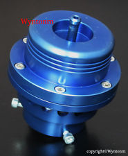
You want one that looks like the one above and not like the one below if at all possible:
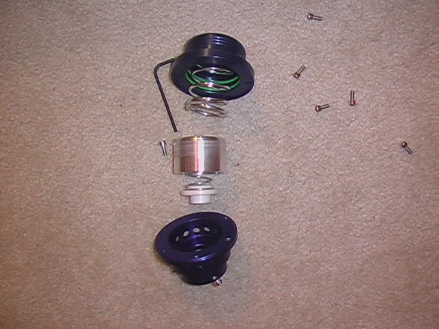
The reason is that the first one has two anodized halves, so if you take it apart, you get two valves out of it for $38.38 total. I got it from a seller on ebay called 'advengers1' who sent it out very quickly. When I got it and took it apart (careful there's a spring inside), it was super cool. I have no idea if it makes a good blow-off valve, but it makes two really cool space suit valves. The bad news is he doesn't sell any in red or the uber cool purple color, but he does sell silver which can be anodized or painted to your color.
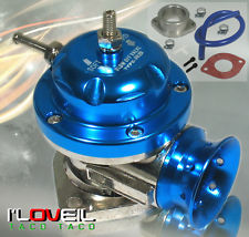
It is the nature of the net that these things go away over time, so if this valve (and I only found just this one), can't be found, make sure you look for a valve with less than a 50mm opening . Anything larger might be too big for your suit. Also, the weight will tend to pull on the material and sag, like udders on a cow. This will only get worse if you make the valves larger. To save money, you could buy something like the PVC valve below at your local hardware store for a couple of dollars and paint it to the color you want:
This is a great solution if you have any artistic talent, because it would be very inexpensive, lightweight and would allow you to express yourself via your art. Here's what the blow off valve looks like opened up. It's very hard to believe seeing this that any blow-off valve could ever cost $600, but there were some for that price online.
Because I wanted the suit to be really good, I had all of the natural aluminum parts anodized. It cost $35.00 for the two neck rings, four wrist wrings and the two halves of the blow-off valves. I should mention that I had the wrist rings machined a little by a friend at work. This would cost more money if you don't have access to that kind of equipment, however, it could be done exactly like the neck ring. The only real difference is that I had a little lip machined into one side to help align the two sides. Here is a picture of all of the parts after they were anodized.
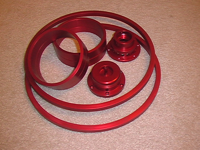
The NASA suits actually use red anodization and blue anodization on the wrists, presumably to keep from confusing right from left. I didn't think of this in time, so I will have to suffer with red on both arms. I can live with that.
01/03/15
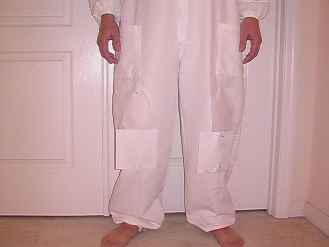
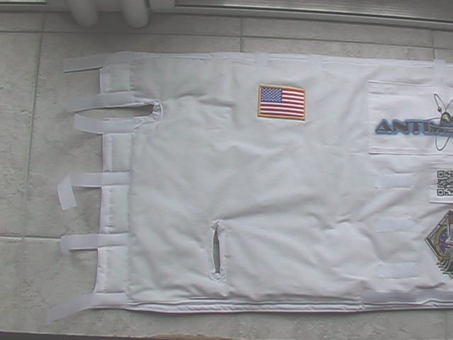
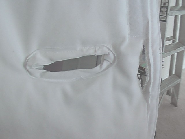
Here are some cut-outs of extra items needed to make the suit look more authentic. The lower pieces of paper will be what appear to be abrasion pads on the original suit. The left leg has a large collection pocket, used by real astronauts for collecting rock samples. The right leg has an odd shaped cover, which on real suits covers the UTC, urine transfer connector. I've decided not to collect my urine in the suit. Instead I will deposit it in the usual fashion.
01/19/15
After attempting to work on the helmet and having difficulties, I turned my attention to the sewing. My wife set up her surger. If you don't know what a surger is, it's a machine used for surging. Ha! Still no help, huh? Surging is what is done to the edges of material to keep them from unravelling. Here's what it looks like.
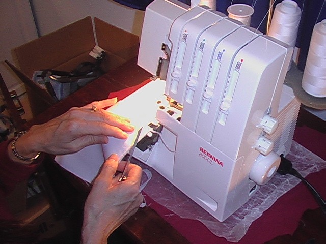
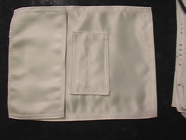
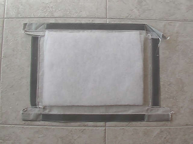
And this is what I made. It's what NASA refers to as the rock collection pocket. Strangely the flap is on the side, but maybe 1/6th gravity isn't enough to make stuff fall out of the side. Who knows. Anyway, it's really three pieces. The top part, the bottom part and the flap on the left. If you look at the seam on the far left, that is what a surged edge looks like. It gets tucked underneath. My wife surged it, but I did the other sewing and for the first thing I've ever sewn, I'm pretty happy with the outcome.
02/02/15
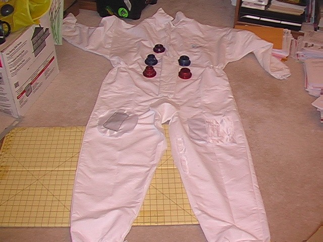
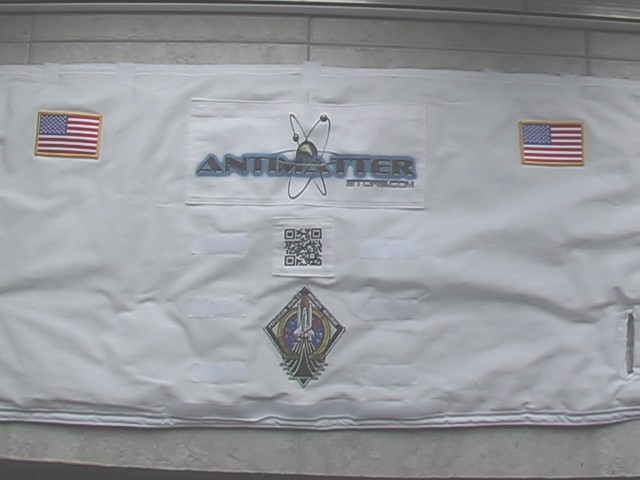
I sewed a few more items and laid them out on the suit to get an idea of what it would look like, but I didn't attach any of them to the suit because I want to keep the suit material flat. My original idea was to have a custom patch made, but that's kind of expensive so I found a place that can print directly onto the suit. For that I think they'll probably need the suit flat. So I'll get it printed and then attach all of the items. I'm pretty happy with the way it's coming along. Here's a pic.
04/26/15
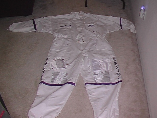
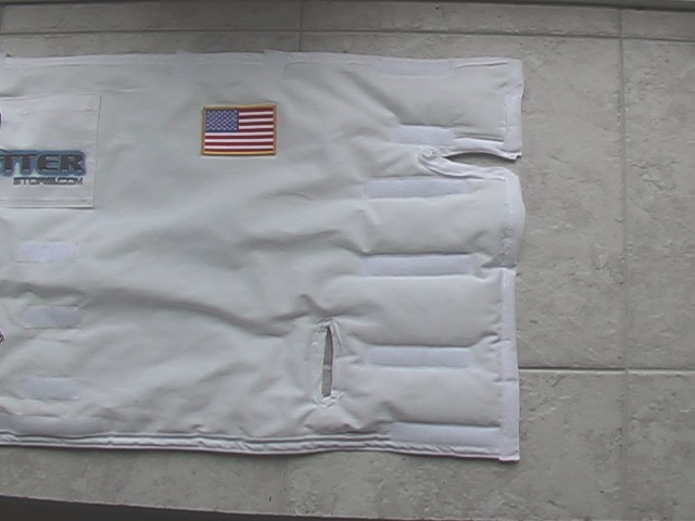
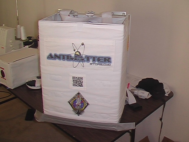
I did a lot more sewing on the main suit. Each pocket requires cutting a little bit larger, then surging around the edges and then finally sewing the pocket to the suit along with the flap. If there is a pocket on the outside of the pocket then it has to be sewn on first. So sometimes even though it doesn't look like much was done, a lot of work might have gone into it. In the photo below, you can see the 'Salvage' logos on the sides of the legs, there is a QR code on the right sleeve and an american flag on the left sleeve that are hard to see. Plus, not in this photo, are the valves, the crotch piece and the adjusting strap. Still, it's coming along.
More to come. . . .
Helmet
12/22/14
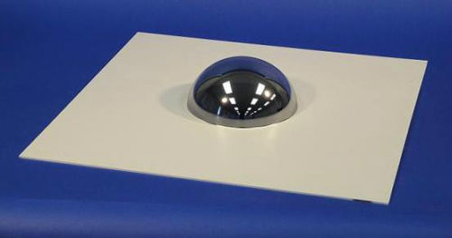
When it came to the helmet, I took a page out of Greg's book and looked up light globes. Before that, I found a relatively low cost ($15.00)video dome on eBay. These can be pricey because they are optically clear.
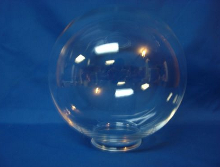
I wound up buying both the clear visor and refelctive visor on eBay. Here's the clear globe I bought. It's anything but optically clear. The picture doesn't show that it has a bit of a seam, but more importantly it's wavy over it's entire surface. It's not so bad that I can't see through it, plus it will be open mostly. It's 10" in diameter and cost $21.95.
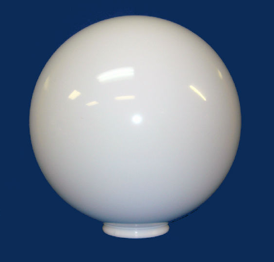
That was originally all I intended to buy, but then I realized it would be much easier to get one more dome for the structure of the helmet than it would be to try to make something. So I found yet another globe on eBay. This one is white and 12" in diameter. I was looking for an 11" dome, but they appear not to exist. Once everything arrived and I got a look at it, I felt better about it working out. This one was $17.50. All of them had free shipping.
It would have been better if the reflective dome was gold, but the silver looks good enough and it has a really freaky effect when you try to look through it from inside. I don't think I'll be walking around like that too much. While you can see through it, you can also see your face reflected in it so I don't think it will be very good for walking around in a crowded con.
The next step was to cut them up to get them in the right shape. You have to get this right or you'll be buying new ones. Because the reflective visor was only a hemisphere, it would require removing the excess flat part. By the time I got to this point, I had handled it a bit. I was careful not to touch the dome part, but the edges got finger prints on them. Do not use paper to clean this. Paper will scratch. I knew that. So I used a microfibre cloth to try to just rub it off. It didn't work.
So I tried a bit of window cleaner.
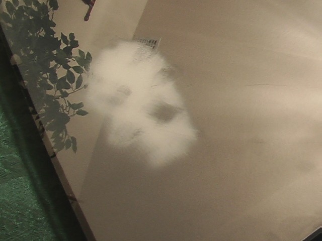
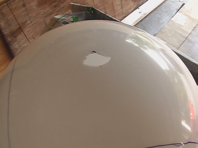
Ironically, the cleaner completely removed the reflective coating, very easily, but did not remove the fingerprints. Go figure. See the fingerprints in the big white splotch? That's why I practiced on the flat portion. I decided to cover both the inside and outside with masking tape. I still need a way to get fingerprints off, because you know it will get fingerprints on it. If I don't put them on, then other people will.
I located the opposite points on the helmet to attach the visor hinges. Then I set out to drill holes at those spots, but I applied a moderate amount of pressure and the globe broke very easily. Be warned, that these things are fragile. Start with a small drill bit at high speed and light pressure. Then work up to larger holes until you have the size you want. Let the tool do the work. This was unexpected, because the globe felt stronger than it was. When they are created, there are spots that are thick and thin. I got a thin spot apparently.
01/19/15
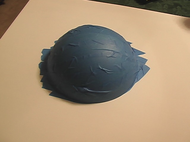
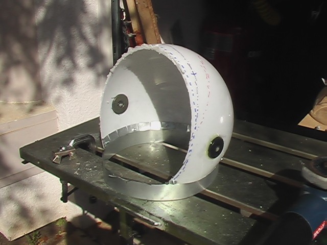
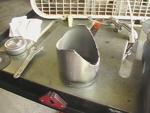
I started off the day on the helmet. It was time to commit to cutting it somehow. The thing is, looking at pictures on the web for ideas, I found dozens of different designs. I could essentially do whatever I wanted. I wanted to stick with a design similar to the Apollo suits so I just looked at those and made my cut. Here's how it looked.
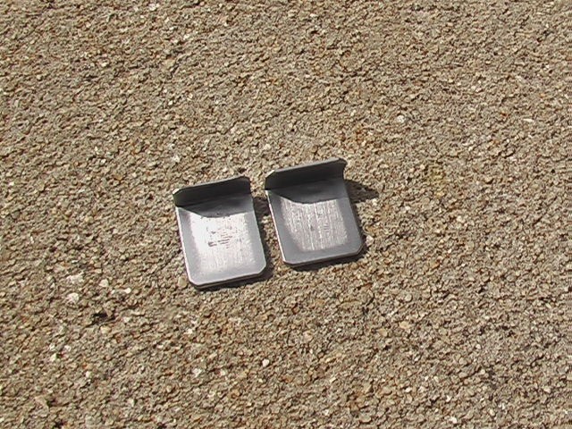
I think it needs a little height, so I'd like to add to the bottom to make it look right. I was lacking the materials for that so I started on the neck ring. I wanted to have some kind of a rest in the back so that when I place the helmet on my head, the neck ring bumps into it to align the two rings. So I figured it out and made these little tabs.
I wanted to tap two holes in the neck ring to mount them and that's where I ran into some trouble. I drilled from the bottom so the neck ring would look smooth from the top. This meant only drilling about 3/4 of the way through the material. When I ran a tap in the hole, I lost track of how deep it was. The tap hit the bottom of the hole and snapped off. With such a shallow depth, I decided I needed to scratch the idea of keeping the top smooth and opted to drill the holes all the way through, because I didn't think I would get enough threads to make the tapped hole useful. I got another tap (6-32) and began tapping out the through holes when the second tap snapped. Only this time it broke right at the surface and I couldn't get the broken piece out. I wasted about 3 hours doing this. I hate tapping holes.
That ended my work on the helmet for the day.
02/02/15
Luckily my neighbor who was there for the tragedy offered to take it to work and have the guys in his shop remove the broken tap and to my surprise, they were able to do it. I guess that's the difference between a professional and a backyard mechanic. So I was able to finish what I was doing. I think I might have a professional tap the other holes I need, too. In the meantime, I made some progress on the helmet.
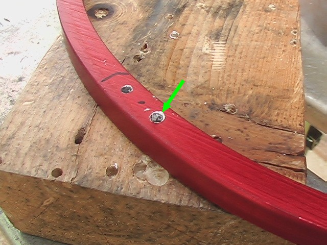
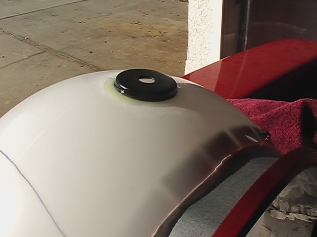
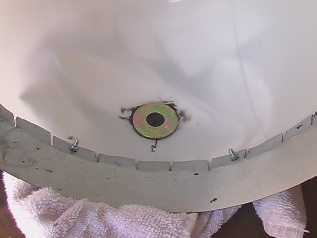
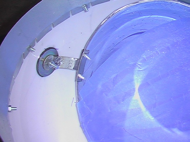
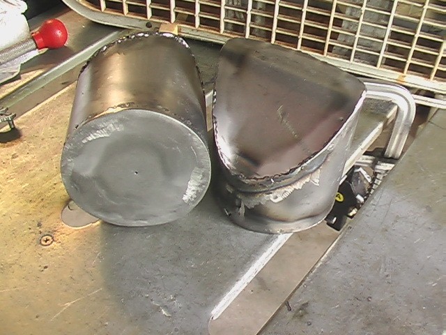
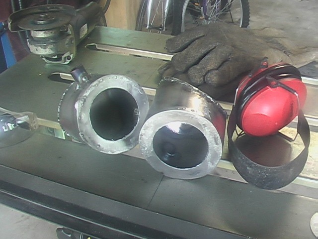
One problem I encountered was that I needed a hole big enough for my head and it had to roughly match the 10" diameter neck ring. When I made that cut, the helmet looked too short to me. The proportions just weren't right for what I wanted to do. I decided to raise it up about 1.25". So I got a 2" strip of steel thin enough to curl into a 10" diameter circle without having to force it around a cylinder. I believe it was 18 gauge. I cut the hole in the globe a little larger, which was difficult, because the plastic was very flimsy. Then in order to attach the ring to the globe, I had to cut little tabs into, like in the picture.
I had to be very careful not to break the plastic, so I used a small bit at high speed and then followed up with progressively larger bits until I had a hole through both the plastic and metal, that was large enough to put a screw through. I used #8 screws (yellow arrow). I used a washer to spread the load and I didn't tighten them very much, again to avoid cracking the plastic. In the end, I plan on covering these screws somehow.
After I extended the helmet, I turned my attention to the hinges for the visors. I started with the one I broke. These parts were junk that were nearly the perfect shape. The cup shape meant that a ring on one side would match up to the curvature of the sphere and the other side was flat which is good to mount thing on. I epoxied it on.
02/08/15
Today, I worked on the neck rings. Here is what the tabs look like installed.
And here's what they look like in action. The idea is to put the helmet on, I just slide the helmet backward until it touches both tabs, then secure it in the front.
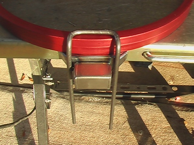
I needed a way to clamp the helmet in place from in front. I could think of dozens of ways to do it and I chose this one. I welded up a sort of hinge for the front that will pivot around a horizontal axis. I bolted it to the bottom ring. The good thing here is if the clamp doesn't work or if I just don't like the look, I can simply unbolt it and come up with a new method. I'd say this is where the helmet varies the most from the NASA design.
Here's the idea.
02/15/15
Some more work was completed on the helmet and some more problems arose. For me this is par for the course. Problems are encountered and overcome. Since I wasn't having any luck with tapping holes, I brought the neck rings into work where a buddy who made the mistake of claiming he was good at it and never broke taps, took care of it for me. Thanks Chris!
I started by reinforcing the mounting points for the visors with some epoxy and large washers.
Next up was creating a way to mount the visor in the helmet. I welded up two brackets and was pretty happy with how they came out.
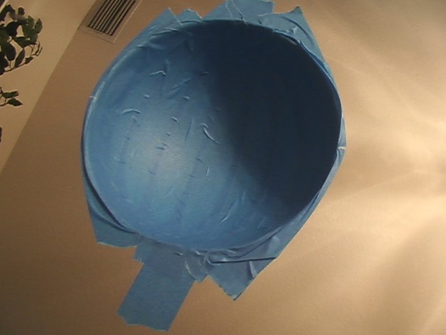
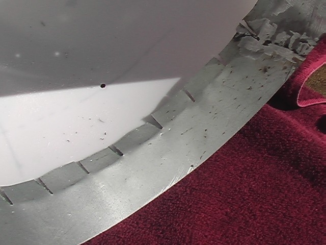
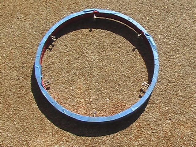
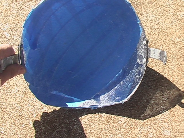
It was about this time that I discovered the blue tape I put on the mirrored visor to protect the mirror finish, while I worked on it, actually removes the finish when the tape is taken off. As it turns out, other than a waste of money it wasn't such a tragedy because the actual tragedy is that the visor was simply too small. As you will see in the following photos. I started by finally cutting the opening. I started small and at this point it reminds me of an old '50s version of a space helmet.
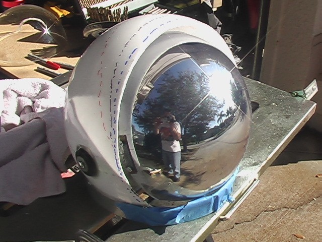
The problem with cutting the opening is that it relies on the size of the visor. But cutting the hole to fit the visor when it is down, could mess up the look when the visor is up. So there is a bit of back and forth between the visor up and down to figure out which should be trimmed first. Here you can see that I put a series of dotted lines on the helmet trying to figure out how to get the visor to fit in the hole in both the up and down position. Ultimately after consulting with images from the web, it looked like the visor needed to be trimmed in the front. Which is what I did.
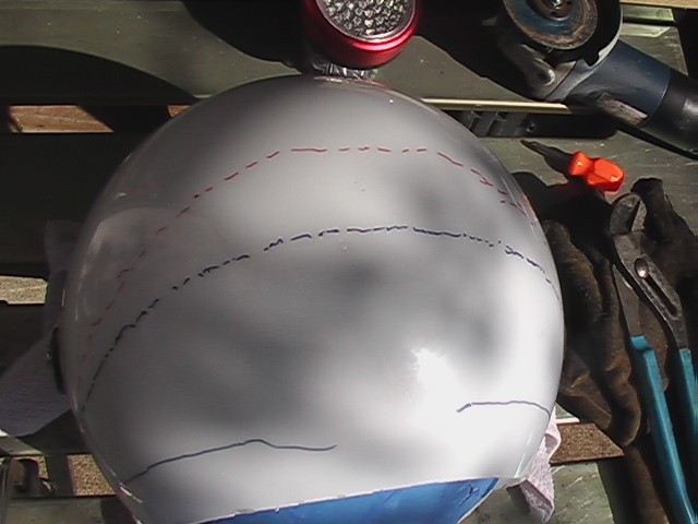
Ultimately after consulting with images from the web, it looked like the visor needed to be trimmed in the front. Which is what I did.
I believe this is the right decision. The shape looks correct to me. Eventually, I had to commit and cut the final hole. The size and shape are ok for the size of the visor, unfortunately, the visor is too small.
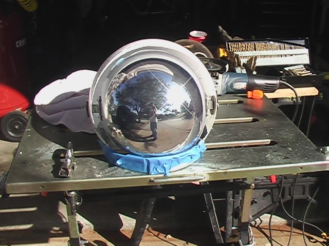
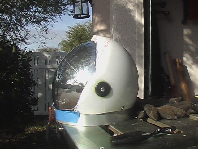
In the next picture I've removed the tape so you can get an idea of what it will look like.
Viewed from the front, you can see how the mirrored visor is just too small for the helmet.
So back to the drawing board.
03/04/15
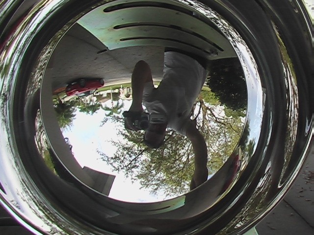
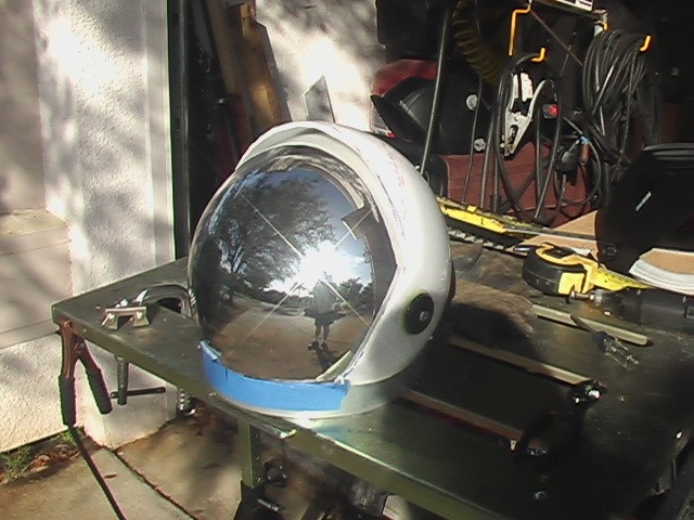
Above is the new 12" camera dome. No I didn't put it in the website upside down. The camera is pointed into the inside of the visor and you will notice two things. First, it's as reflective inside as it is outside, which means you both see through it and see your reflection which in the wrong lighting conditions can make it hard to see out at all. Second, the image is upside down, making the view out, even weirder! It gets a bit better when my face is deep inside, but it's still a very strange effect. The next challenge was in getting it to fit.
Below, I've fitted the visor, but doing it by sight is very difficult. It's hard to tell if the pivot line is in the right place, whether it's crooked, whether the visor is cut right. There are many variables that are not only hard to measure, but hard to even conceptualize. It does look a lot better, though. Unfortunately in this configuration it doesn't open more than an inch or so.
I decided to enter it into Autocad to see what it should look like under ideal conditions.
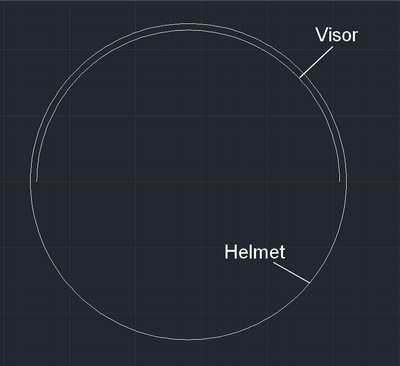
If the mirrored visor and the white globe I'm using as a helmet were just the right size so that they would nest like the picture above, There would be no problem at all. I tried to go down that road, but because they are only available in 2" increments, there was just too much room between the helmet and the visor and it looked stupid.
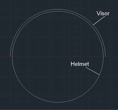
Instead I have the case you see below, where the visor is technically a bit larger than the helmet.
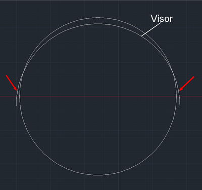
To get it to fit, I first have to move it down, which leaves some bits hanging over (red arrows) as you can see below.
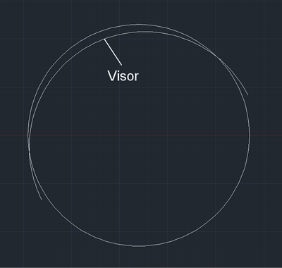
I rotated the visor into the position I want it. The front is to the left. Of course, at this point there are still some pieces hanging over.
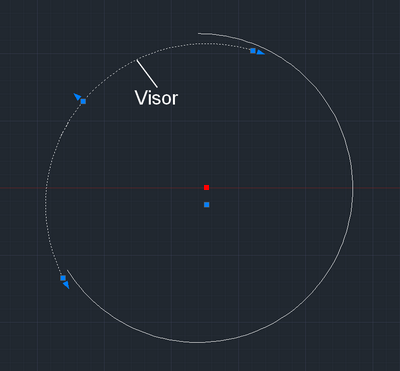
In the next picture, I've removed a portion of the helmet, where the visor would fit and I've removed the extra part at the back of the visor. I've done this just by memory of approximately how I did it in reality. Nothing is precisely measured. It's important to note that the center of the visor (blue dot) and the center of the helmet (red dot) are no longer co-located, since I have moved the visor down. So when the visor is attached, it needs to be done so that it pivots about the helmet's center.
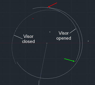
Next, I rotated the visor around virtually to see where there was interference and it showed me that as long as it's properly centered in the helmet it shouldn't have any interference at the back at all (green arrow). In fact, if the visor is rotated to the point where the back is at the same height as the front, the interference is at the front of the visor (red arrow).
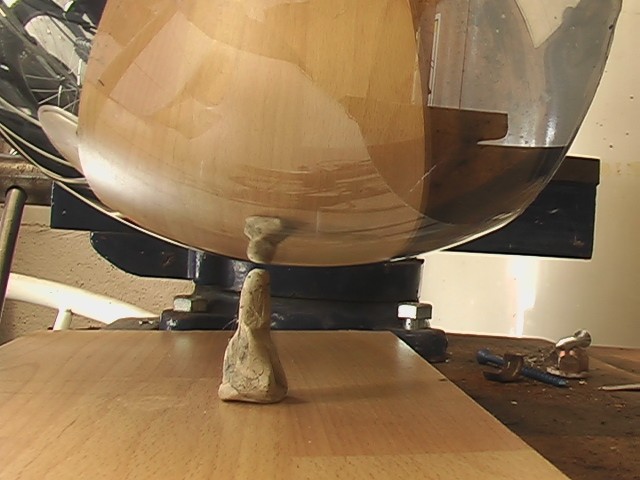
Given this information, I had to find out what was wrong with my helmet. I suspected the line of rotation was off. To test it, I removed the visor and put a rod through the two holes. Then I attached a stick to the rod, making it long enough to get close to the helmet. The rod allowed me to rotate the stick along an arc. Here's what I discovered.
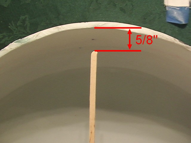
The clearance at the top of the helmet is 5/8".
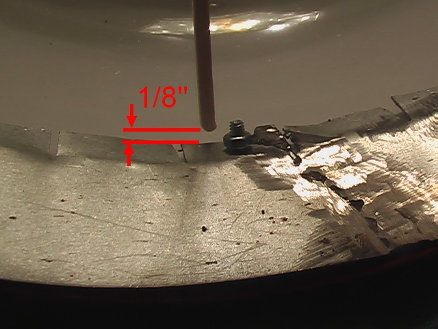
The clearance at the back of the helmet is a little more than 1/8". So the pivot line needs to move 1/2" forward to provided constant clearance all round. Or does it?
The reason I say that is because this doesn't take into account the pivot point on the visor. The problem could be that the pivot points on the helmet are wrong, in fact, they are, but it could also be a combination of errors. I don't know that the pivot points on the visor are any more symmetrical than those on the helmet. I need to repeat this test in reverse with the visor. And just as importantly, I can't be certain that either the visor or the helmet are not exactly spherical. To fix this problem I'll need to do more investigation. And. . . once I do all that and fix it, I still have the inner visor with which to repeat the whole process. Arrrgh.
03/29/15
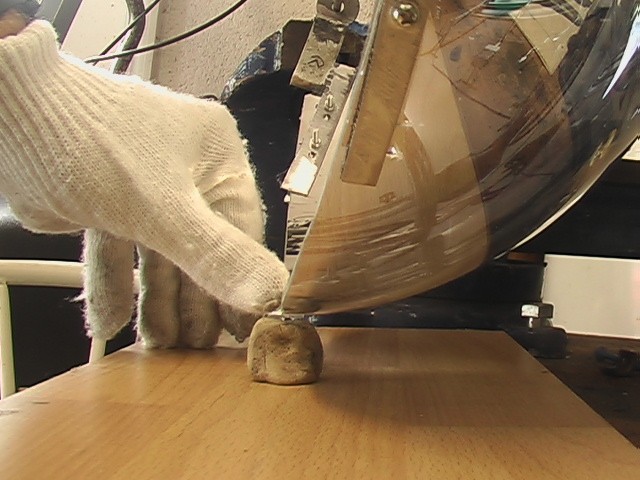
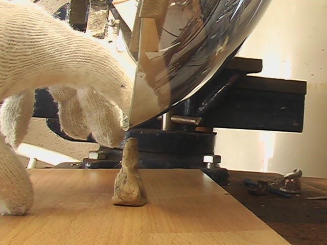
I haven't updated in a while, but I have been working on it the whole time. I'll continue where I left off. After measuring the inside clearance with rotation, I did the same on the outside.
I suspended the visor on a rod clamped in a vice and rotated it through its full range of motion. Below is where it is closest to the clay I have placed below it.
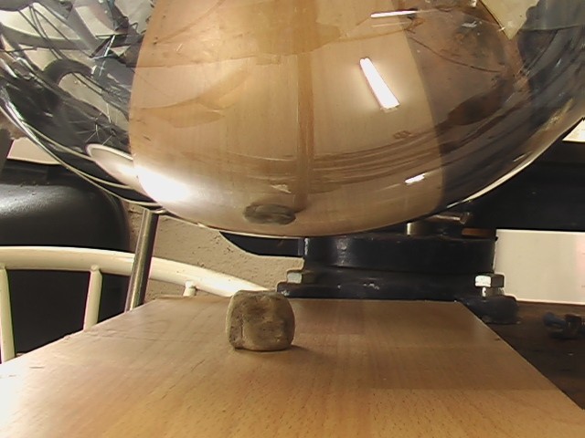
And this is how far away it comes from the clay at its furthest.
I made some adjustments and things got much better. Notice I'm wearing cotton gloves here. I got them at Harbor Freight.
The neck ring seemed to sit around my neck like a necklace. I wasn't sure I could get it to sit properly by just securing it to the suit. When I looked online I noticed that on some astronauts the ring was down where a normal collar would sit and on others, it seemed to be up by their chins. When I attached my helmet it seemed to move around a bit. I felt a structure was needed to position the helmet. This is what I made.
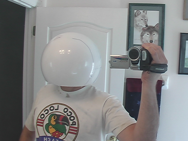
04/26/15
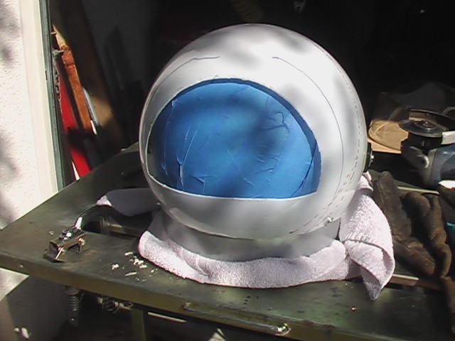
The point of all of the alignment was to make sure that the visor rotated insided of the helmet without going wonky on me and dragging on things and basically causing problems. I was about 3/4 the way through with my build when I found another guy that built a historical replica of Jim Lovell's space suit. That lucky guy had a real NASA helmet to work with and he made a visor that fit it perfectly. If you have that ability, I highly recommend that route. I was working with existing parts. In the end I had to leave the inner clear visor out altogether, because, the difference between my helmet and a real space helmet is that my visors were on the inside of the helmet, which meant that I had to have space above my head for the visors to fit inside of the helmet. That necessitated the neck ring structure to lift the helmet up and away from my head. I think trying to mimic the real thing would be a better way to go, if you can. Instead, what I got was a helmet that looked awesome when the visor was closed, but not so great when it was open. I think it's more important to look good when the visor is closed, so I will live with the compromise. Here is what it looks like in its finished form. My wife helped me with the covering and it came out awesome, I think.
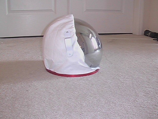
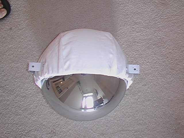
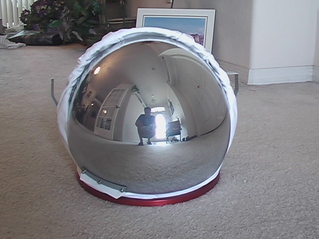
And here it is with the visor up.
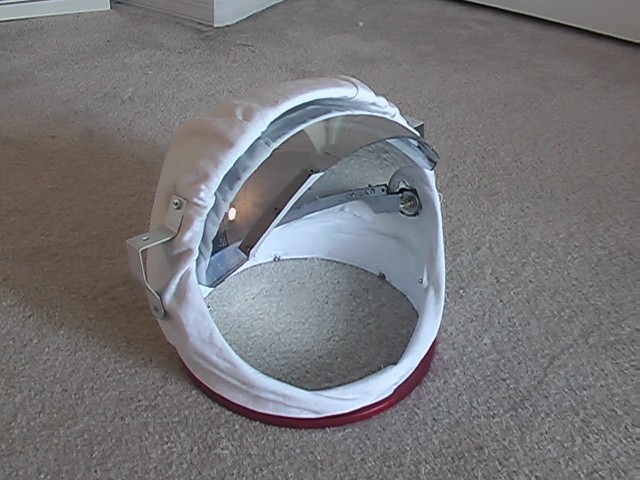
It's very difficult to cover the helmet with fabric, because the fabric is flat and the helmet is spherical. A stretchy fabric would work ok, but I wanted a bit of a loose fit, like NASA had. It took a long time to get the folds in the right place. The fabric is held in by sandwiching it between the neck ring and the inner metal ring. There is also quite a bit of fabric glue involved. I think it came out great. It's not quite tall enough, which is another reason I needed the neck ring structure, but I like the look and I added some camera and lighting mounts.
I added a little hand hold to close the visor.
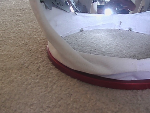
On the neck ring I created a narrower neck because the collar would not quite fit around the existing one, you can see the curved pieces (red arrow). Also, you can see how the material is sandwiched between the two rings, just like the helmet.
Backpack
04/26/15
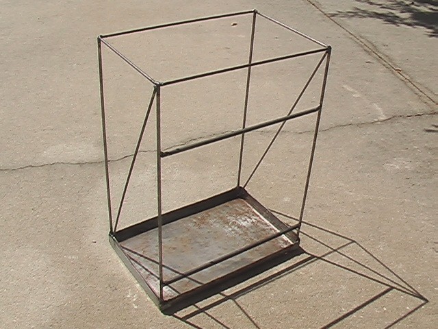
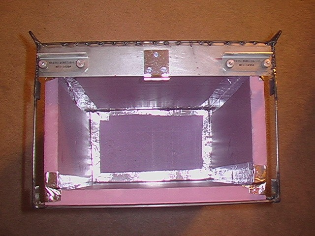
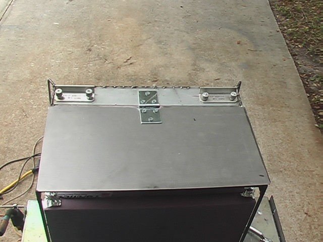
The backpack became a necessity when I determined that the cooling shirt was a necessity. The water/ice mixture needed to keep me cool would have bulged too much and looked too ridiculous just contained on my back under the suit. I made it mostly out of scrap. The bottom is a cookie sheet, very hard to weld to and the rest is essentially 3/16" rods welded to create a box, which was lined with 1" thick home insulation. I taped the corners and made a little top, that wedges into the box. Here are pics of the build.
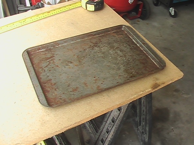
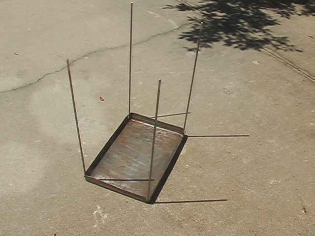
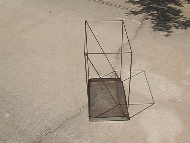
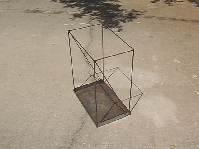
The thin sheet metal of the cookie sheet was so hard to weld, I blew some holes in it and wound up beefing it up with a couple of strips of steel I had in the garage. I also added a piece on the top using the same strip, to mount the water and electrical connections.
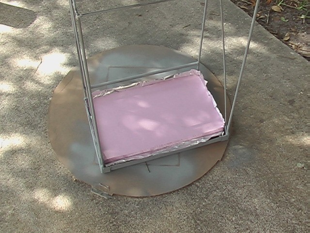
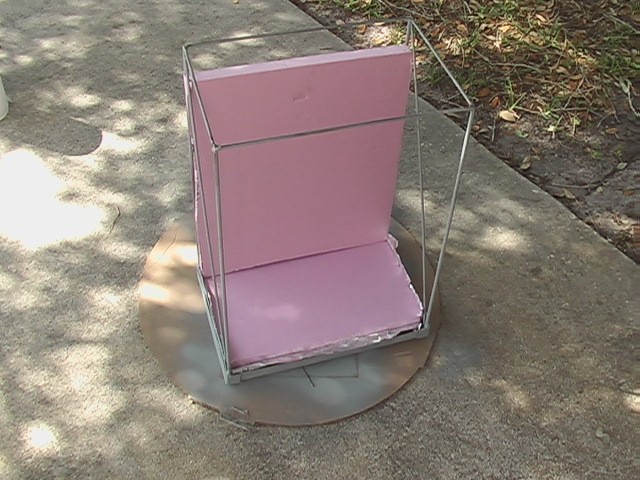
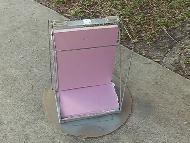
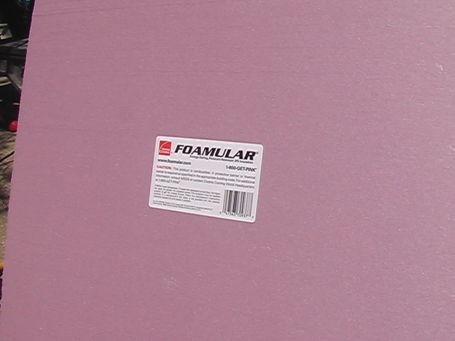
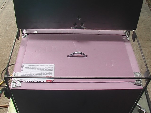
Here is the foam I used. It was cheap at Home Depot, available in 2'x 2' sections that fit in my car. I was able to cut them with a circular saw but I had to move fast because lingering would cause the foam to melt. Also, the paint I used on the metal caused the foam to melt. I actual foresaw that and tested, it but I only used a light coat. When I put it on a little thicker, it melted the foam. Just be careful.
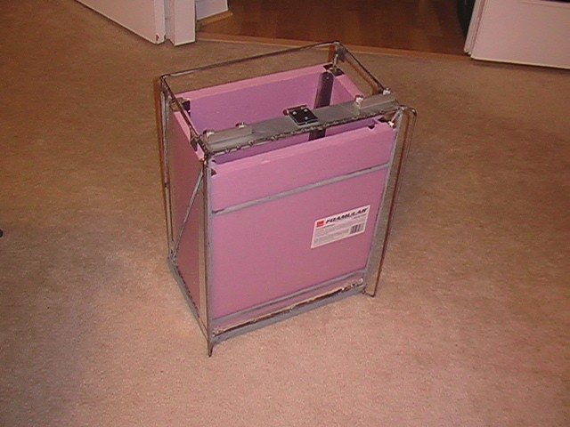
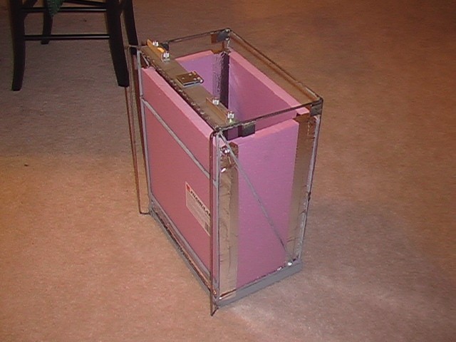
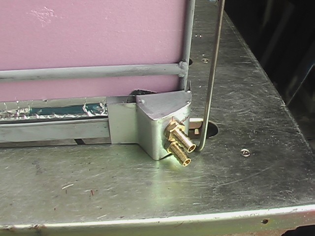
I made little enclosures for some nipples. Yes, I said nipples. Tubes attach to these and wrap around the front of the suit to the valves. They are non-functional.
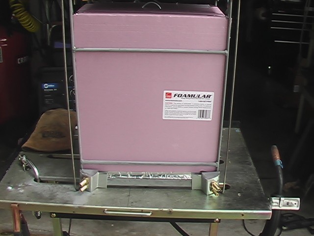
I made a lid. It has to open because the foam box has to hold the water bag, which will be a solid block of ice. I tested this principle with the amount of time I thought it would have to last if I were to leave my house and travel to MegaCon and the thing was still solid. I'll probably have to add water to it when I get there, the cooler works so well.
This box gets wrapped in batting to make it sort of padded and then with cloth that's got some cool stuff sewn on to it. Like this:
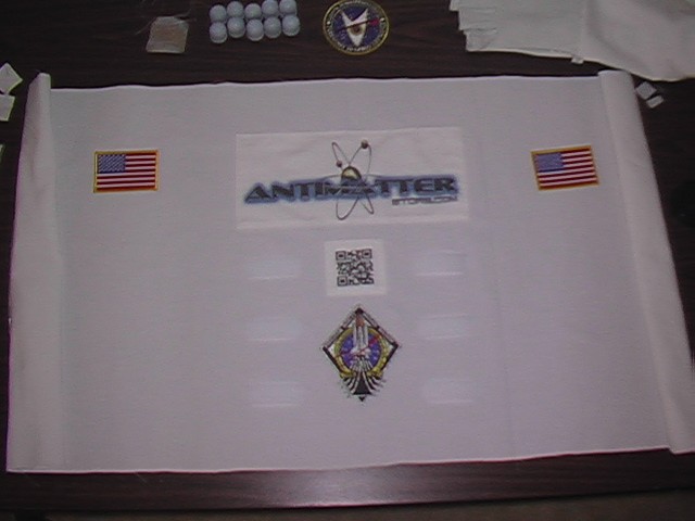
The American flags go on the sides.
07/26/15
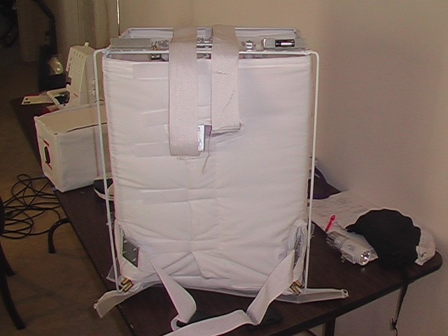
A lot has been done on the back pack. I've added some straps. It's a bit industrial, since I took some strap material I got at Joann's fabrics and made some metal plates. I threaded the strap around the support bar and wrapped it back on itself, then sandwiched it between the metal plates using some bolts. I did this because otherwise I would have had to hand sew the straps since you can't put the whole pack on the sewing machine. In retrospect, there are probably better ways to do this and I think the plates might cause the straps to wear faster where the edge meets the fabric. For now I'll leave it. How often am I really going to wear this thing anyway.
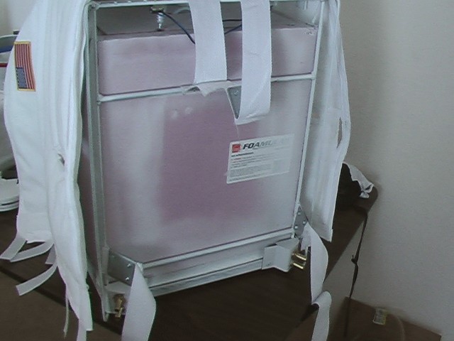
To put the cover on the pack all of these extra parts need holes and slits so it will lay right. I also wanted the cover to have a padded look so I put a couple of layers of batting inside. There were many, many steps to get to this point, sewing three button holes and cutting them into one long one, sewing bias tape around holes (not easy), attaching all kinds of velcro, etc. Anyway here is the final product.
As you can see it looks a little wrinkly with all of the handling I've given it, but that's ok. That's the way things from NASA look, plus when I tighten it up some of the wrinkles come out. Here is a close up shot of the slits.
And here it is wrapped around the pack. Velcro on the front side will not be seen since it goes against my back and allows me to tighten it snuggly around the pack. You can see I added a some velcro tabs that wrap around the top supports to keep it from sliding down. It's almost done. Just have to do the top and bottom.
I'm super happy with the look. I'm less happy with the look of the bottom piece, which I'm making out of ironing board material. You can see it mostly done in the pictures above. Here is what it looks like as I was making it. I put a little bit of padding in the bottom.
That's not all there is to the pack. The bottom pack just holds the water for my cooling system and the pump that circulates it. I was still going to need some daily supplies for my day at MegaCon, like some food, batteries, tools to fix the suit in case it broke, antimatter pellets, yellow cake uranium, small particle accelerator, you know, the usual stuff you bring. So I also made a top box. I started by bending up some sheet metal.
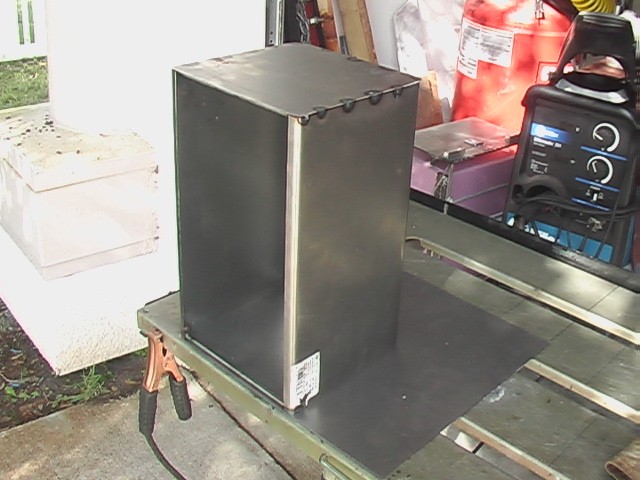
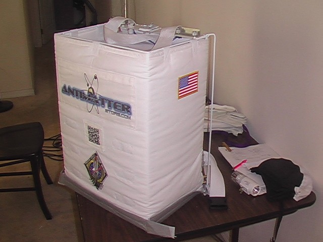
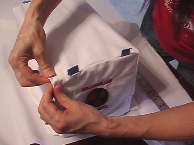
Apparently I didn't take too many pictures of it. I'm not sure how that happened but it's a pretty basic box. I looked around to see if I could just buy these boxes, but I didn't find anything that was just right and inexpensive enough. The top box has four feet that stick out to the sides. I drilled holes through them and into the top of the bottom pack so I can bolt the top one to the bottom. Then it was covered in the white fabric with a couple of warning symbols. In case you are wondering, a while back I wanted to know if there was a warning symbol for antimatter and it turns out that there wasn't. But there was one created by a physicist and in the years since I first looked, the symbol seems to have gained some traction, being used in a video game and a couple of other places. You can check it out here: Astrowright. He also sells these little patches, of which I bought two and sewed them on. Pretty cool, huh?
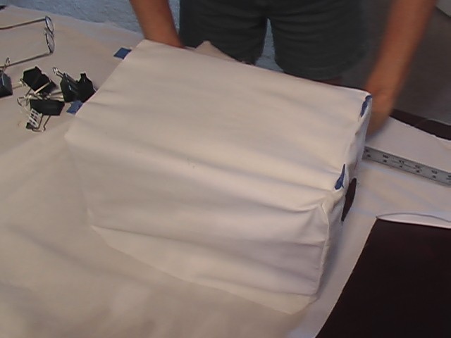
Above you can see it being covered. The little blue tabs are the feet that attach to the lower pack. They are blue because I put tape on them. I had to bend two of them to get them into the covering. No biggie. Here's another shot.
Cooling Shirt Build
09/20/15
There are some trade-offs that need to be considered with making your own cooling shirt. At this point, I'm still not sure I will use one. The biggest trade-off is, will it be more uncomfortable to be hot, or to carry around 30 lbs on my back all day. According to some research I did on some websites where people have made their own to use in race cars, I would need about 2 gallons to go all day. I figured due to weight I would load my dromedary with 1.5 gallons. If I ran out of ice, I think some would be available at a vendor. Water weighs about 8 lbs per gallon, so the water alone would weigh about 12 pounds. The entire rest of the pack weighs about 7 pounds bringing the weight to 19. The top pack only weighs about a pound and a half but the speakers and speaker boxes are about 2 more pounds. Finally, I will need to carry a few items, so I think the pack is pushing 30 pounds. I'll have to weigh it when I'm done to be sure, but as I said, it depends if I use the cooling system at all.
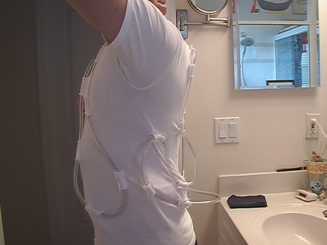
Another decision to be made is the size of the tubing. After doing some research I opted for vinyl 1/4" ID tubing. This is good and bad. The bad part is the tubing is stiffer than the shirt can handle. Stringing the tubing through the shirt on a hanger just causes the shirt to twist into strange shapes. The only way to get it to work at all is to don the shirt and run the tubing. Even that was a struggle. The bend radius of the tube was also large so that only a few runs could be made up and down the front and back, very few. The good part is that so few runs meant that the length of tubing is shorter, only 20 feet. I expected twice that. Here's how a first attempt at the shirt went.
To secure the tubing small loops of a stretchy bias tape were sewn to the shirt, like this.
Here are some shots of how it looks on. Obviously some modifications would be necessary. But there are more serious problems.
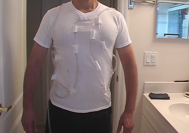
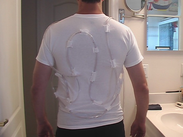
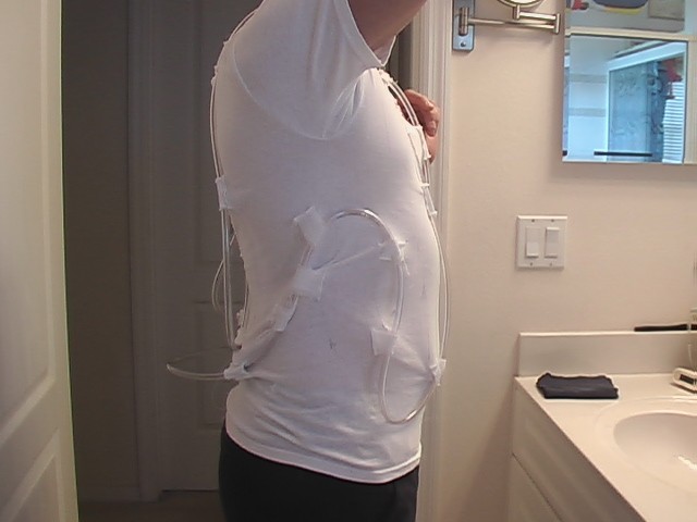
In places the bias tape is pulling away from the shirt as you can see.
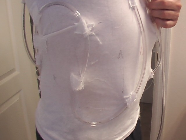
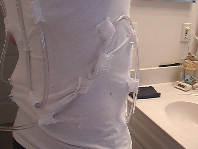
Attaching a few extra securing spots will help hold down the tubing and the rest of the suit will also help hold it in place. I was able to plug the fish pump into the tubing and run some ice water through it and I can say that even as sparse as the tubing is, I could feel the effect and it was pleasant. Not too cold, not too useless. I was afraid that it might be cool on my front side (the input) but warm going out on the back, but I didn't notice that at all. What I did notice is that it is far more effective if the tubing is touching the skin. I think a better idea would be to sew the tubing on the inside of the shirt. That would put the tubing against my skin and hold it down nicely since the shirt is tight.
The biggest problem was that the pump only ran about 5 minutes on the little 12V battery. It wasn't completely new, but it had plenty of juice left in it. That means that I would probably need a larger capacity battery to run the pump all day. That means yet more weight.
This little pump barely gets the job done and only if it's provided a full 12V and primed.
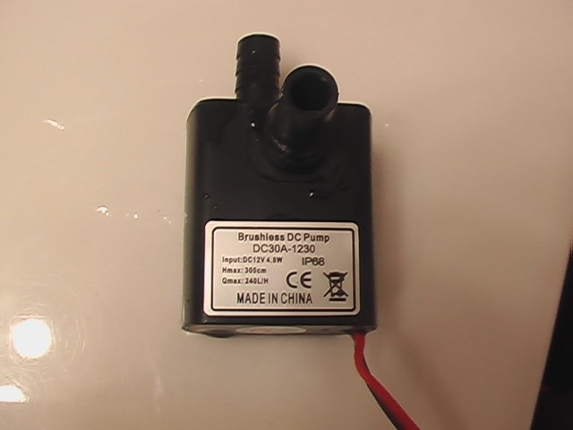
Here's the setup in the backpack. The red arrows are quick disconnect connectors, with shut-offs. The blue arrow indicates where the little 12V garage door opener battery goes.
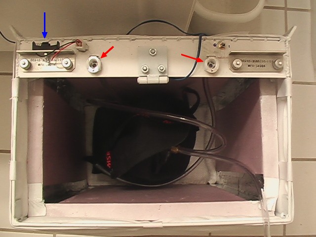
This little pump barely gets the job done and only if it's provided a full 12V and primed.
Audio
09/02/15
To really complete the space suit I needed to make some noise. I hopped on the old DARPA net and found this little sound board on the cheap. You really don't need much in the way of experience to use it because the Adafruit website is pretty thorough in their description.
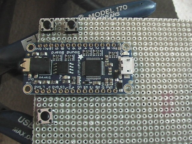
I opted for this one which was a total of $27.00 shipped: Sound board. If you plan to only do a few sound clips like me, you can easily get along with the 2MB version, especially if you are using OGG files, which it seems to prefer.
To use it, you simply use a USB phone charger cable, the kind that comes with many phones and are pretty easy to come by, to connect it to your computer. Don't power it. I had problems when I powered it. The board will draw current from the computer. Then you simply upload your sound bites into it. Do this one at a time. The onboard processor is slow. You can load up to 11 files. I recommend short bites because once you play one, it plays until it is finished. So if you play a 3 minute song, you better be ready to listen to the whole thing. There is a spot for a mute button, but you still won't be able to play other sounds until it finishes. I loaded mine up with sound bites from NASA. The quality isn't audiophile for certain, but it's way better than one of those birthday cards that plays sounds. It was perfect for NASA sound clips and what I wanted to do with it. Something else that wasn't mentioned on the Adafruit website is that if the sound clip is too loud or is played too loud, the sound will pop and cut out in intervals. All you have to do in this case is lower the volume until it plays smoothly. It's a good idea to make all of your sound clips about the same volume so that you don't have to continually adjust the volume. Other than that, the only thing needed is a number of momentary switches of your choice and a 3 to 5 volt power supply for the sound board. Batteries work. Keep reading to find out how I did it.
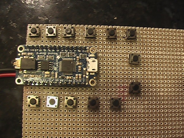
In the photo above you can see the small momentary switches I used. They come in many formats. I used these because they were small, but then I spaced them wide enough to be able to press them with my gloves on. I got 20 of them for $4.00 on ebay.
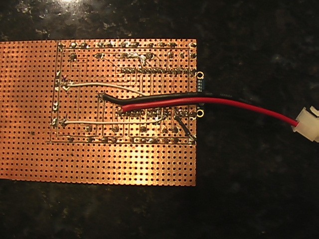
While the board requires little skill attaching all of the parts can be an issue if you aren't familiar with electronics. A soldering iron and a mass of wires would probably work. I had this perforated PCB that worked well. Where I work we would normally use artwork and an etching bath to make the traces, but I'm not allowed to use them. Kits can be had from places like Radio Shack, but a ruler and an exacto blade also works, but you'll need a microscope. At least I did. Every time I cut the board to form a gap between traces, I checked continuity between the board and the trace to make sure nothing was shorting out. I did this often and when I was done, I methodically checked every connection. Then after I soldered things, I did it again, which was a good idea, because I had a solder blob that shorted things out. It isn't pretty, but it really gets the job done and I think I can use the holes to sew it into my suit.
Here's a picture of the top side. The buttons on the right are volume up and down.
The board comes in two versions. One has a built in amplifier. Because I figured MegaCon would be pretty loud and a 2 Watt amplifier wouldn't be up to the task, I bought the cheaper one with no amplifier so that I could add my own. To keep costs low, I went on ebay and bought this one. It was $7.00 shipped.
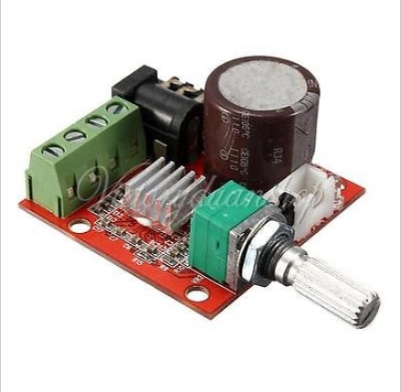
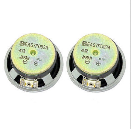
There are tons of them on ebay and it has two 10W stereo channels. Again, it's not audiophile quality but it sounds quite good for a $7.00 amplifier. And when you have an amplifier, you need speakers. Because this wasn't going to be a hi-fi 3 way system, I decided to size the speaker at something close to 3", to hit the middle of the range. It was difficult finding something cheap that would handle the power in that size. I found the 2.75" panasonic speakers below, on ebay for $12.00. They sound good but didn't have holes to attach them. I had to get creative to secure them. I wouldn't recommend them since four screws would be a lot easier than figuring out how to mount them. I kind of assume they are normally held in place by a speaker cover or something.
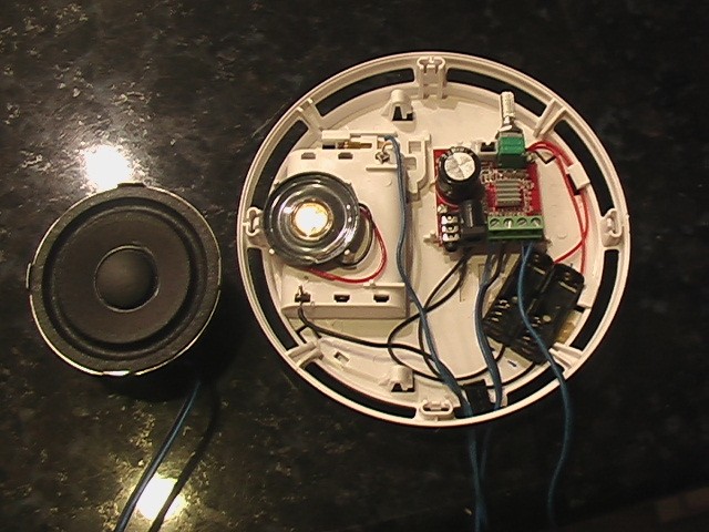
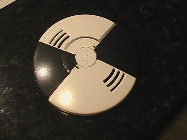
One thing to note about the amplifier is that it is powered by 12V, so you'll need something other than the power supply for the sound board. I was already using 12V batteries to power the cooling system, so it wasn't a problem for me. I mounted the amp and it's batteries in an old smoke detector that I painted up to look space suity.
The next thing needed for the sound system was speaker enclosures. I decided to make some custom enclosures that would match the suit. First I came up with a concept.
Then I just worked the idea until it came out the way I wanted it to.
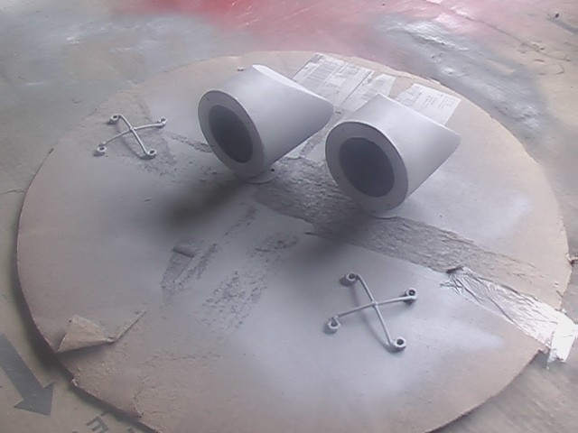
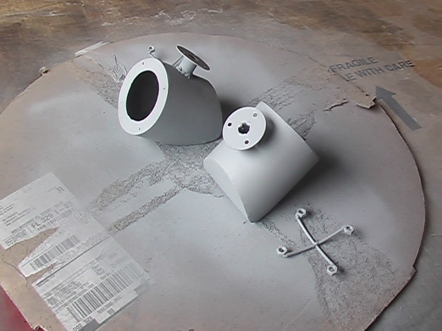
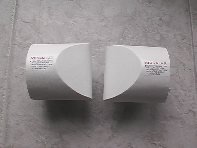
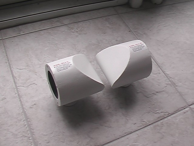
A little paint and a decal that I printed on my printer, finishes them off.
More to come. . . .